Zurich Kloten [LSZH] 02.10.2003

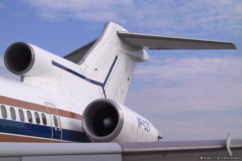
Boeing 727-2P1 (WL) (A/RE) (Super 27) (msn: 21595 / 1406) mfy: 1979
VP-CZY
Untitled (Dunview Co.)
History:
1979 Qatar Airways Amiri Flight A7-AAB
1996 Comtran N727MJ
1997 Dunview VP-CZY
- Pratt & Whitney JT8D-217C/17 (BFG)
The Pratt & Whitney JT8D is a low-bypass (0.96 to 1) turbofan jet engine, introduced by Pratt & Whitney in February 1964 with the inaugural flight of Boeing's 727.
Design
The JT8D is an axial-flow front turbofan engine incorporating dual-spool design. There are two coaxially-mounted independent rotating assemblies: one rotating assembly for the low pressure compressor (LPC) which consists of the first six stages (i.e. six pairs of rotating and stator blades, including the first two stages which are for the bypass turbofan), driven by the second (downstream) turbine (which consists of three stages); and a second rotating assembly for the high-pressure compressor (HPC) section, which has seven stages. The high-pressure compressor is driven by the first (upstream) turbine, which has a single stage.
The front-mounted bypass fan has two stages. The annular discharge duct for the bypass fan runs along the full length of the engine, so that both the fan air and exhaust gases can exit through the same nozzle. This arrangement allows some noise attenuation, in that the still-hot fast-moving turbine exhaust is shrouded in much-cooler and slower-moving air (from the bypass fan) before interacting with ambient air. Thus the JT8D noise levels were significantly reduced from previous non-turbofan engines, although the low bypass ratio meant that high noise levels were still produced.
Eight models comprise the JT8D standard engine family, covering the thrust range from 12,250 to 17,400 pounds-force (62 to 77 kN) and power 727, 737-100/200, and DC-9 aircraft. More than 14,000 JT8D engines have been produced, totaling more than one-half billion hours of service with more than 350 operators making it the most popular of all low-bypass turbofan engines ever produced.
Within the fan inlet case, there are anti-icing air bosses and probes to sense the inlet pressure and temperature. Similar units exist throughout the engine to check temperatures and pressures.
At the 13th (i.e. the final) compressor stage, air is bled out and used for anti-icing. The amount is controlled by the Pressure Ratio Bleed Control sense signal (PRBC). The diffuser case at the aft end of the compressor houses the 13th stage. Its increasing cross-sectional area allows the compressed air to slow down before entering one of the engine's nine burner cans. Again, there are two bosses to extract 13th stage air for anti-icing, de-icing of fuel, and airframe (cabin pressurization) use. Not all the compressed air enters the burner cans at the fuel-ignition point; some bypasses the can completely and cools the first turbine stage, and some is gradually introduced into the burner can's perimeter in such a way that the burning fuel is held near the can's centerline.
There are nine combustion chambers positioned in a can-annular arrangement. Each chamber has three air inlet hole sizes: the smallest is for cooling, the medium is for burning and the large for forming an air blanket.
-
Canon Powershot G3
____________________________